In this article, we will have a look at infill, how it works and some of the available patterns before exploring how we can use it to enhance models, inform designs and create art.
This guide covers:
- What is Infill in FDM 3D Printing?
- Infill Pattern Types
- Slicer Software Preview and Settings
- Behind the Walls
- Without Walls
- Structural Integrity
- Creating Art and Other Uses
What is Infill in FDM 3D printing?
Unless printing in vase mode it is likely that you will, at some point, have come across infill in your 3d printing journey. Infills are repeating patterns of extruded filament created by your slicer to fill in the gaps between the walls of your prints. By using infill, 3D printers can create strong, light models that use less filament than if the model had been printed solid.

(Image: Natalie Cheesmond)
Infill Patterns
A variety of infill patterns have been designed, some for strength, in one or all of the axes, some to minimise filament usage, and some to increase the speed of the print. PrusaSlicer and Cura alone provide you with a choice of over twenty patterns. The patterns can be a single or double-layer repeat or more complex and three dimensional in nature so let’s have a look at a few of the more common examples.
Grid
The grid pattern is one of the simplest infills with a single repeating layer in the shape of a grid. The pattern is fast to print and provides strength through the z-axis but less so for the x and y axes.
(Screenshot: PrusaSlicer)
Concentric
Similar to the grid pattern concentric infill also has a single layer repeat. The path of the infill follows the walls of the model creating a pattern that mirrors the model’s shape. It adds little strength in the x and y axes and although it has some strength in the z axis, its not nearly as strong as the grid pattern as it has no overlapping lines. Concentric infill does however provide aesthetic uniformity when using transparent or translucent filament.

(Screenshot: Cura Slicer)
Gyroid
Gyroid infill changes the direction of the infill pattern on each layer. It uses rows of parallel wavy lines to create infill that over height create a 3D structure not dissimilar to a series of curled tunnels or tubes. The benefit of this 3D structure is that it has approximately equal strength in all directions (axes), is quick to print and has a low filament expenditure to strength ratio. The gyroid pattern is also found in molecules and crystalline structures in nature.

(Screenshot: PrusaSlicer)
Aesthetic Infill
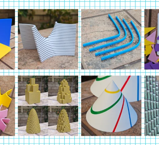
Apart from its raison d’être as a structure to fill the gaps in 3d printing, infill can also been used to enhance the aesthetics of designs and to define them. Transparent and translucent filaments allow us to see the infill behind the wall and thinning or removing the walls altogether give us an even more dramatic effect. So lets have a look at how to use infill pattern and density when used for decoration rather than structure.
Slicer Software Settings
Before exploring infill further, it is worth mentioning the role your slicer plays in this type of print. You will rely heavily on the slicer previews to give you an idea of how your model will look once printed and to assess whether the model will successfully print. You can control the type and density of the infill through your slicer as well as the thickness of your walls and top and bottom layers. Your slicer also determines which infill patterns you have available to play with. The settings we will talk about adjusting in the following paragraphs are infill pattern and density, wall count (vertical shell perimeters) and top and bottom layers (horizontal shells top and bottom).
Behind the Walls
A design printed in transparent/translucent filament will show the infill behind the wall to some degree, but how you use this will depend on what you are trying to achieve with your design. You may want the light to shine through your model or you may want a mottled or opaque effect. You may choose the infill pattern so as not to detract from the shape and feel of the model, or you may decide that the infill is going to be the star of the show. Dependant on what you are looking to achieve you might consider different infill patterns and densities.
The nature of the infill pattern can impact opaqueness. Repeating patterns create areas of solidity and complete transparency and can appear very bold if used at low density. Three dimensional patterns tend to create a more uniform opaqueness particularly if used at higher densities. If you are looking for a subtle mottled patterning a 3d pattern such as gyroid or cubic at a relatively high density (>25%) should be your go to.

(Photo: Natalie Cheesmond)
If you are looking for the infill to shine through use striking patterns at lower densities (<25%) and reduce your wall count to 1. You can choose to use infill patterns that compliment your model shape or jar against it to enhance the effect, for example a pyramidal model will look very different with a stark angular rectilinear infill when compared to a curvaceous gyroid pattern.

(Image: Natalie Cheesmond)
Without Walls
What if we want to print without walls (or top and bottom layers) allowing the infill to shine through and define our model?
The nature and density of the infill patterns that we looked at in the previous section still apply. Repeating patterns will create dramatic models, at least viewed from certain angles and 3D patterns will create softer gentler effects. The infill can also now fundamentally change the shape of your model and orientation joins density and pattern as an important impact factor. We also need to consider structural integrity so let’s explore these further.
How to Remove the Walls
Choosing which walls to remove is important when making an infill design. Some designs, such as concentric, need a horizontal wall (top or bottom) otherwise the pieces will fall apart, as the extrusions don’t overlap and are not connected. Removing bottom layers may also make your first layer more difficult to print in some instances. Removing vertical walls is a good place to start but you will need to play with the settings particularly for curved models.

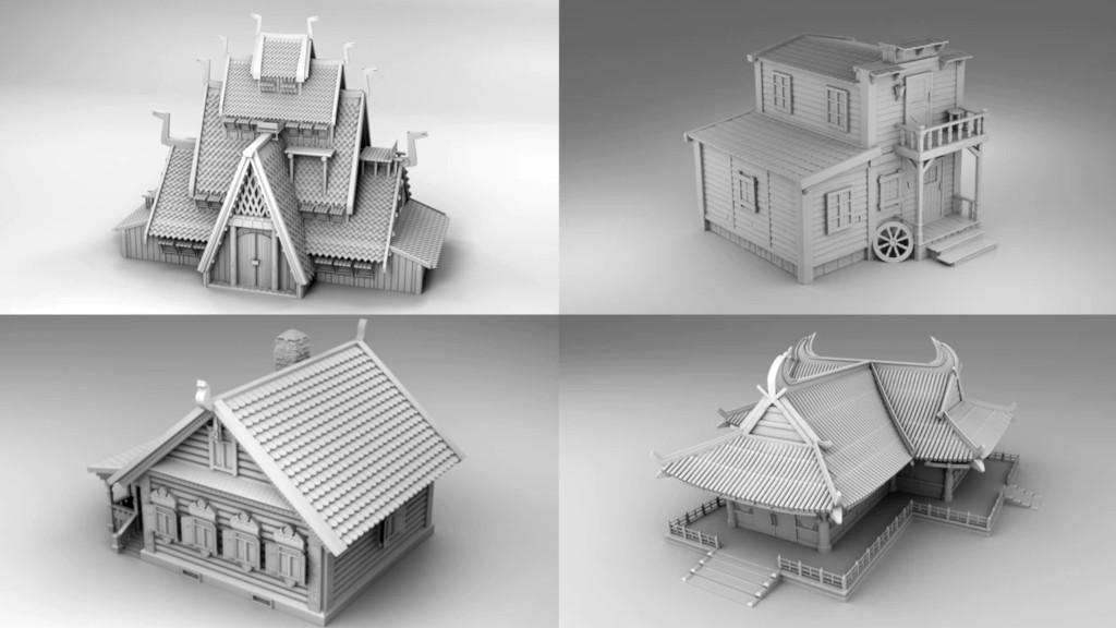
Pattern Orientation
Orientation of your model can make a massive difference to its final look. For example, by rotating this building model, printed in aligned rectilinear infill, along the Z axis, we change the frontage from a plain wall to something much more intricate.

(Image: Natalie Cheesmond)
Similarly, this tower model looks rather boring in original orientation but when flipped 90 degrees in the y axis and sliced in concentric infill it has a completely different look.

Structural Integrity
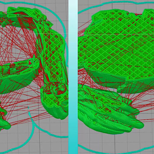
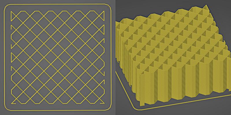
Finally, we need to consider the structure of integrity of the model, its printability and sturdiness. When we look at our sliced model we need to ask: will this print?
The main factor that may stop an infill model printing successfully is the existence of extrusions that are not supported from below. Infill is designed to be attached to the walls in a normal model and may struggle without this support. Where we have unsupported extrusions in the core of a model increasing the density can alleviate the issue.

Where the sliced model has unsupported extrusions around the periphery or ‘hanging edges’ increased density is less likely to get rid of the unsupported extrusions but will make them smaller. It is also worth playing with z axis orientation as this can help in some cases.

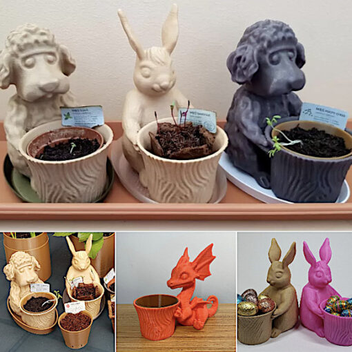
Creating Art and Other Uses
When designing for infill, perhaps the most important thing to do is to experiment. Experiment in your slicer with density, pattern, orientation and wall thickness. Experiment by printing too, sometimes hanging edges and unsupported extrusions create patterns of their own that enhance your design.

(Image: Natalie Cheesmond)
Finally experiment with your models, this lampshade design was the direct result of a failed vase print!

(Image: Natalie Cheesmond)

(Image: Natalie Cheesmond)

(Image: Natalie Cheesmond)
The models and designs featured in this guide were printed on Original Prusa MK3S and Voxelab Aquila S2 (affiliate links). Follow 3DPrintBunny on Patreon to get early access to exclusive designs and generally to support creative 3D printing


You can see 3DPrintBunny’s designs on Thangs.
For more artwork, please visit the 3DPrintBunnyArt website.
Read more: Silhouette Art – How to Design and 3D Print
One of the best things about 3D printing is the opportunity to create your own designs and art projects. In this guide, I am going to share some simple techniques I use to create silhouette art and some ideas on how we can use these techniques for more complex projects.