Text-flips are clever 3D printed models where one object intersects with another and the shared volume becomes the final print. In this guide, we look at how text-flips work, the two main types of text-flip models, and how to design your own using OpenSCAD.
Table of Contents
- What Is a Text-Flip?
- Inspiration From a Leading Text-Flip Designer
- The Two Main Types of Text-Flip Models
- Software Used – OpenSCAD
- How to Design a Text-Flip That Combines One Word With Another
- How to Design a Text-Flip That Combines a Word With a 3D Object
- Print Settings
- Final Thoughts
What Is a Text-Flip?
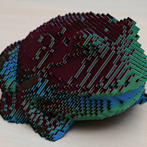
A text-flip combines a text object with another object where the two intersect or cross one another. The second object can be another word or a simple 3D shape. Once both objects overlap correctly, the intersecting volume is kept and exported as the final model.
Such designs are highly customizable and, depending on the desired size and volume, can be printed quite quickly on both budget resin and FDM 3D printers.
Inspiration From a Leading Text-Flip Designer
I would like to give credit to master__printer. I was introduced to the idea of a text flip through their designs; you can download their designs on Cults3D. I learned to design my first text-flip model when someone in the comments of a Reddit post explained the process, and I have had fun creating my own text-flip models ever since. I focus on designs that are personal to me.

The Two Main Types of Text-Flip Models
There are two main approaches to text-flips. One combines a text object with another text object. The other combines a text object with a 3D object. Both follow the same general principle: create overlap first, then keep only the shared volume.
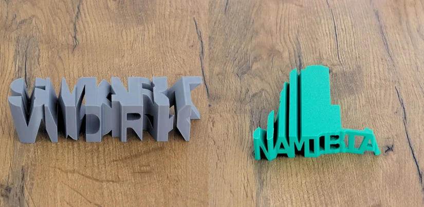
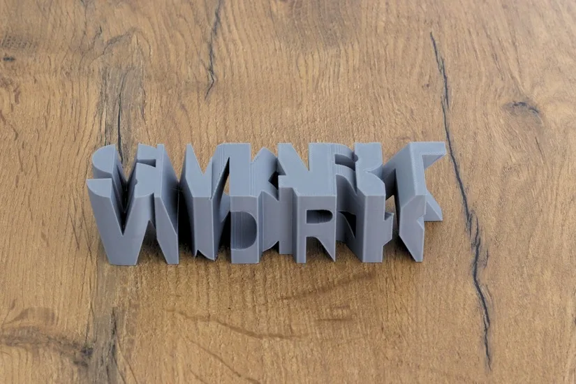
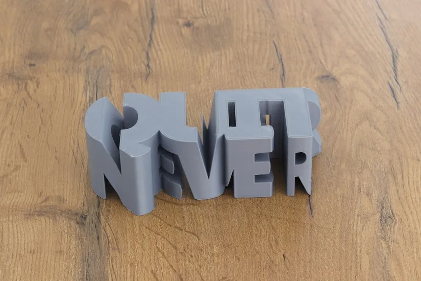
Combining a Text Object With Another Text Object
This version uses one word intersecting with another word. It is a good starting point because the workflow is simple and easy to understand once the text alignment begins to make sense.
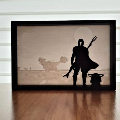
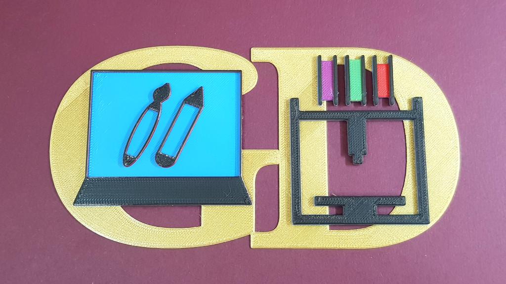
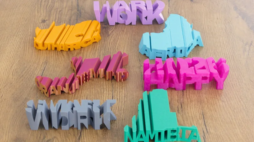
Combining a Text Object With a 3D Object
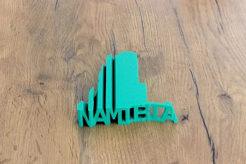
This version uses a word and a shape, such as a map outline or silhouette. It opens the door to more personalised models and more creative combinations.
Software Used – OpenSCAD
In this article, I will explain how to design a text flip using OpenSCAD, which I use to design my text-flip models, but the process is applicable to all CAD software. This tutorial explains the process in Fusion360.
How to Design a Text-Flip That Combines One Word With Another
This example shows the process of combining two words into a single text-flip model.
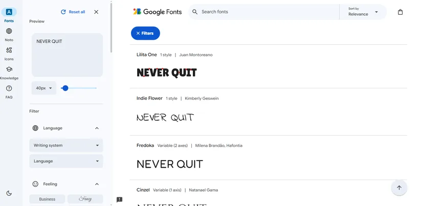
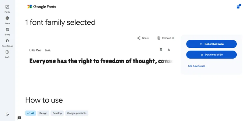
Choosing the Font
Start by browsing Google Fonts and testing your words in uppercase. Bold and black fonts usually work best because they produce thicker letters that print more reliably. Even spacing also helps, as you will later reduce the tracking slightly in OpenSCAD so the letters overlap and become one connected shape.
The two words do not need to have the same number of letters. You can compensate by adjusting font size, extrusion height and position during the design stage.
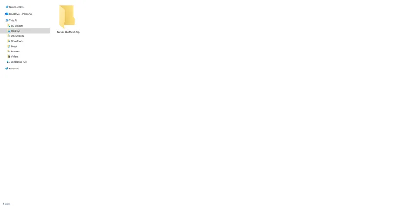
Preparing the Project Folder
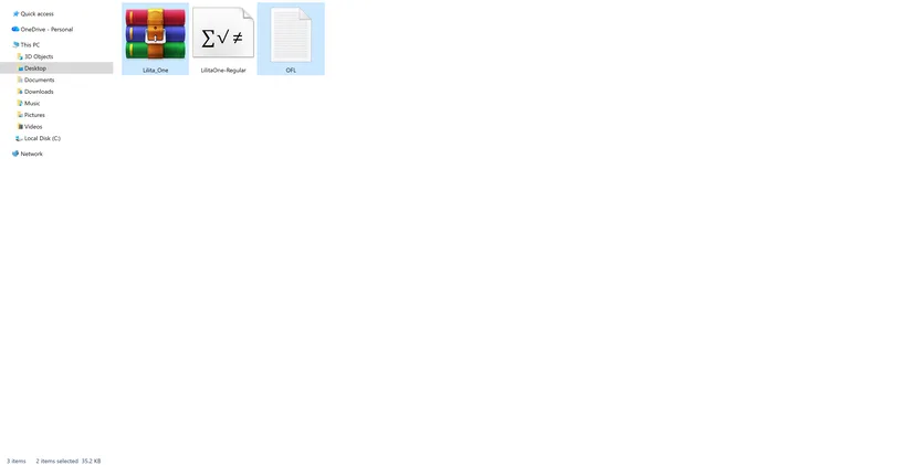
Create a new folder for the project, copy the downloaded font zip into it, extract the font, and remove any unnecessary files. Keeping each text-flip in its own folder makes it easier to manage font files, the OpenSCAD file and later STL exports.
How to design the text-flip in OpenSCAD
Start by downloading and installing OpenSCAD; you can download it here. Open a new OpenSCAD instance and save your new .scad file in the folder you have created, give it the same name as your text-flip.
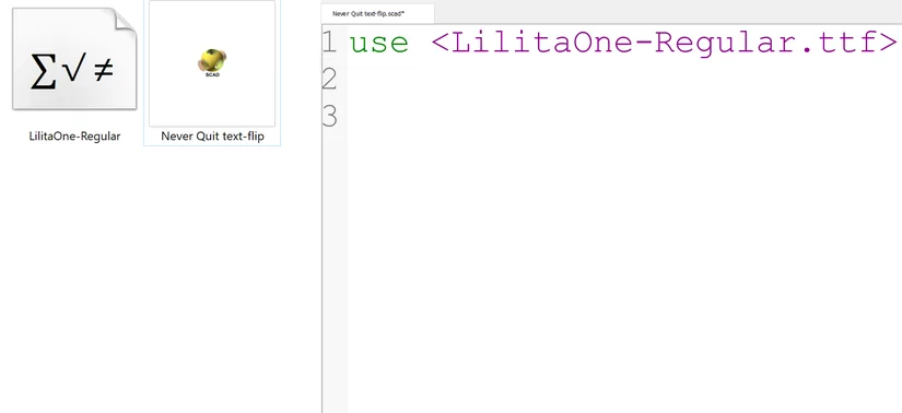
Importing the Font Into OpenSCAD
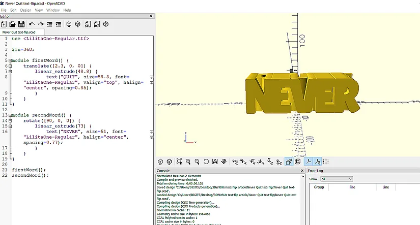
Open a new OpenSCAD file and save it in the same project folder. Import the font using a use statement and make sure the file name in the code matches the font file name exactly.
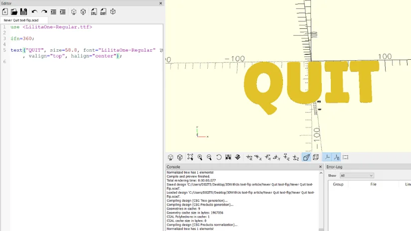
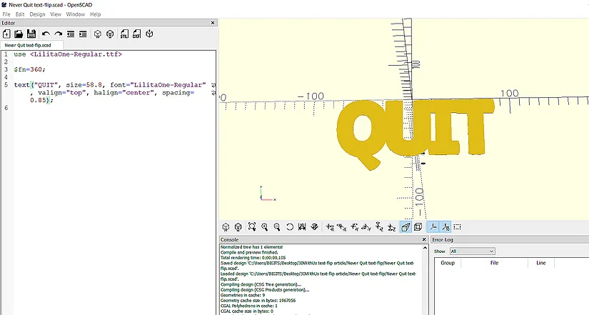
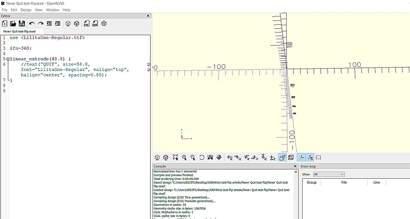
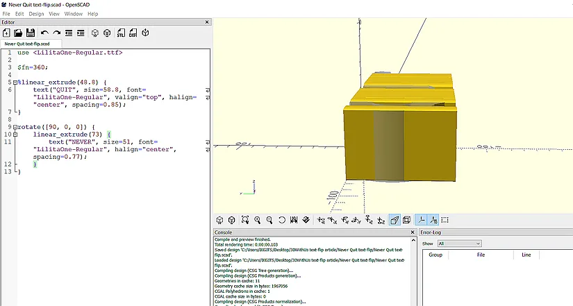
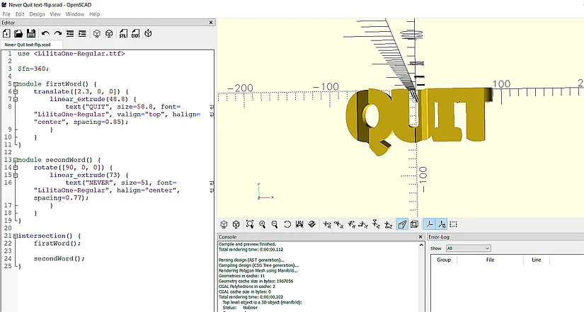
Setting Up the First Word
Begin with the first word. Set the text, font, font size, and position. A high $fn value helps keep curves smooth. Then adjust the spacing so the letters overlap slightly and form a more stable printable object.
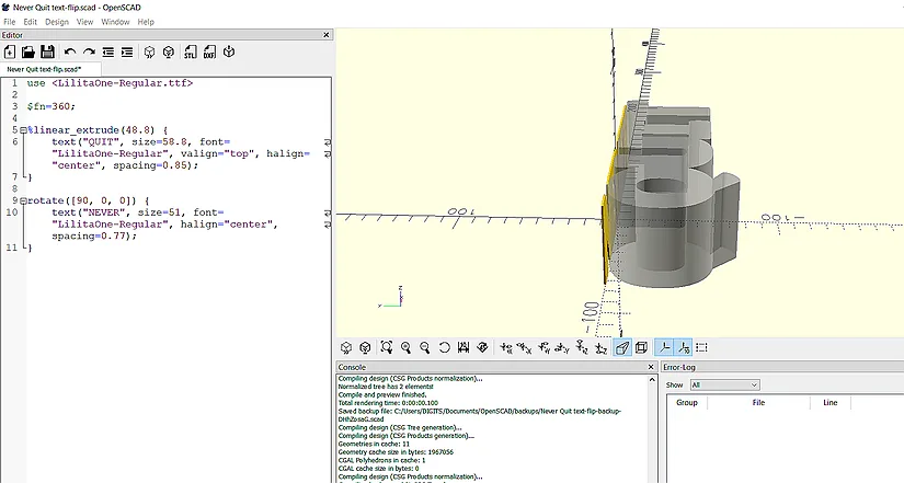
Turning the Word Into a 3D Object
Once the text looks right in 2D, wrap it in a linear_extrude function to give it thickness. This turns the flat word into a 3D object. After that, temporarily comment it out so you can build the second word without visual clutter.

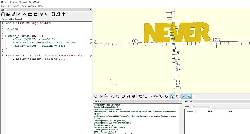
Setting Up the Second Word
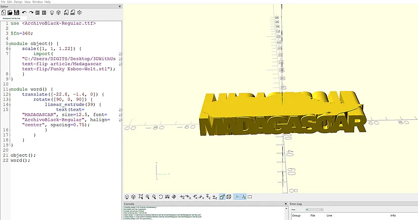
Create the second word using the same method, then rotate it 90 degrees on the x-axis so it faces forward. At this stage, you are preparing it to intersect with the first word.
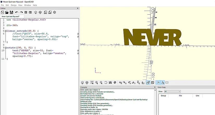
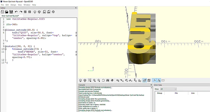
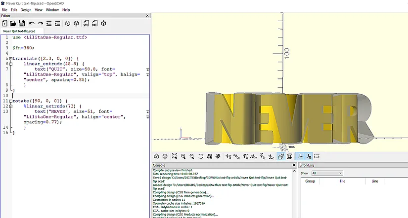
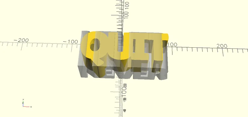
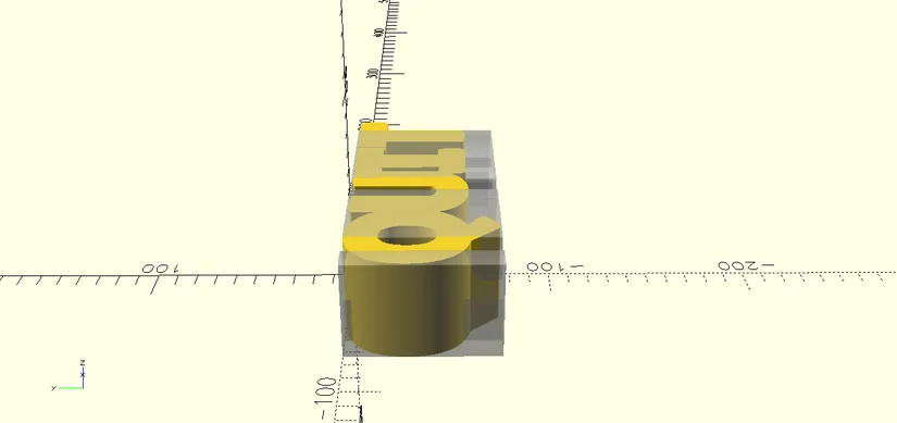
Checking Overlap Between Both Words
Make the first word transparent with the percent modifier, then extrude the second word until it overlaps. Move between side, front, top, and perspective views while adjusting translate values, font size, and extrusion until both words intersect in the x, y, and z axes.
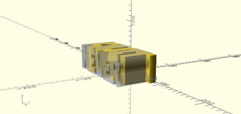
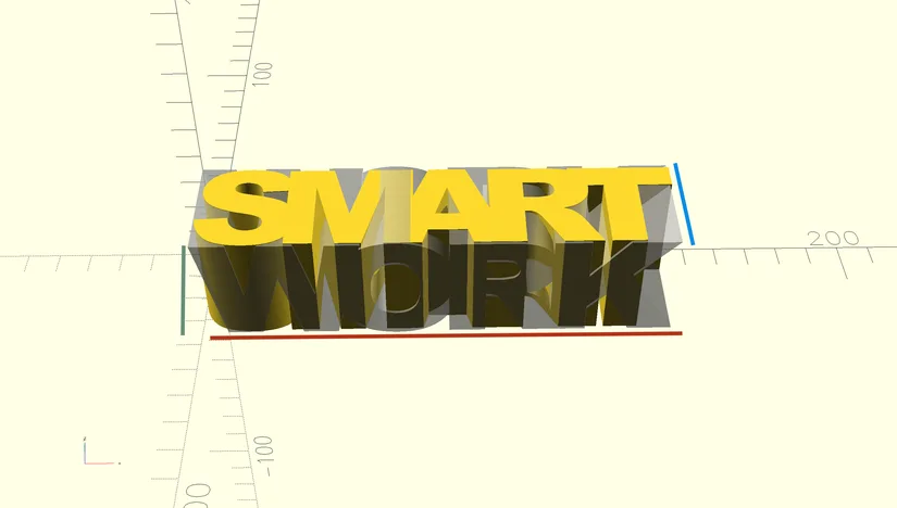
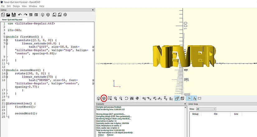
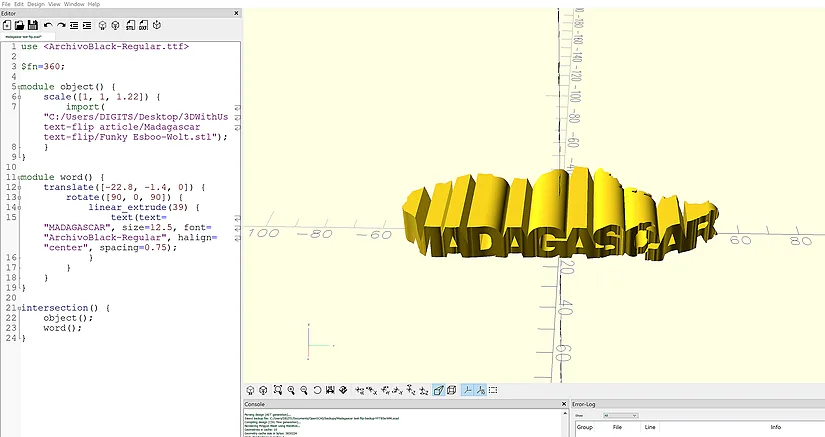
Creating the Final Intersection
Once the overlap is correct, remove the temporary visibility modifier and place each word inside its own module, for example, firstWord and secondWord. Then call both inside an intersection function and render the model. OpenSCAD will keep only the geometry shared by both words, which creates the final text-flip.
Exporting the STL
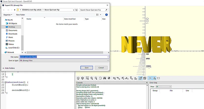
After rendering, export the finished text-flip as an STL file. If you are using an OpenSCAD nightly build, it is a good idea to type the .stl extension manually when saving.
How to Design a Text-Flip That Combines a Word With a 3D Object
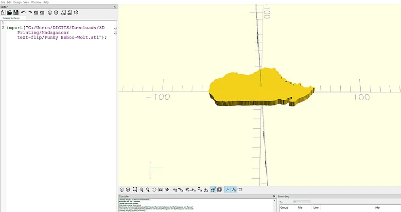
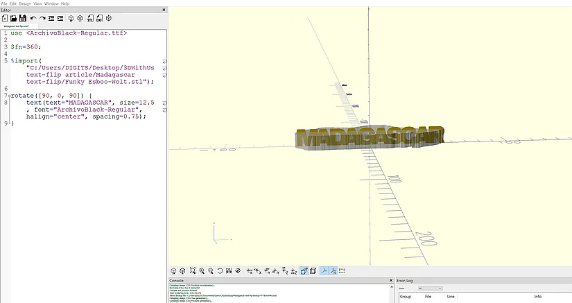
This example shows the process of combining text with a simple shape. In this case, the second object is based on the outline of Madagascar.
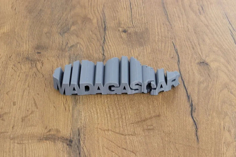
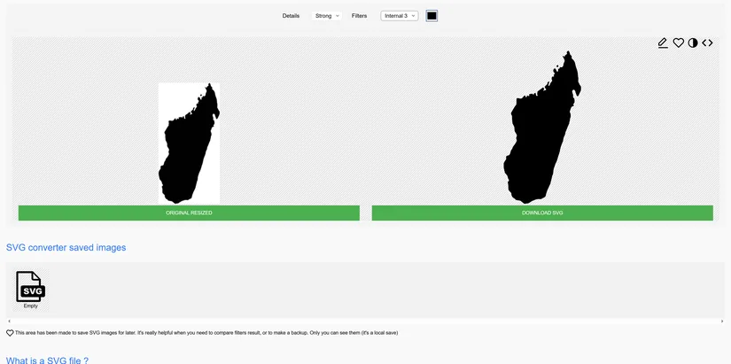
Creating the 3D Object
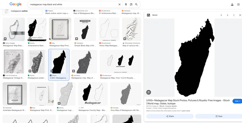
A simple way to make a usable shape is to start with a black and white image. Search for a clean outline, save it, and convert it into an SVG. This creates a shape that can be brought into Tinkercad and then exported as an STL for OpenSCAD.
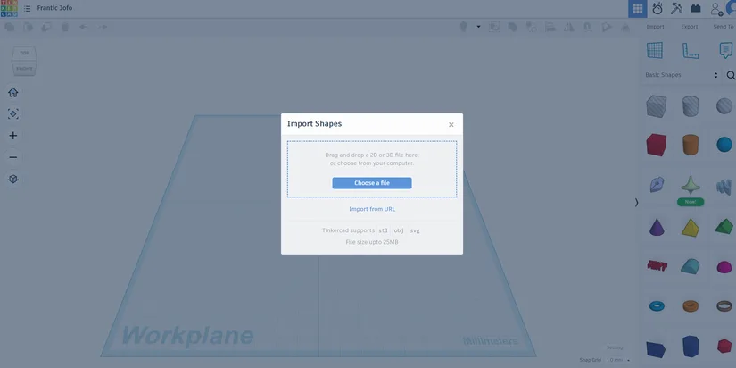
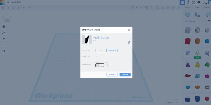
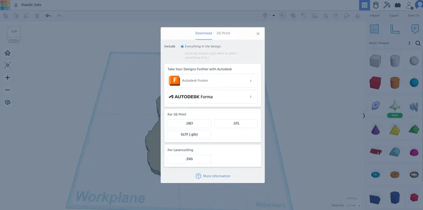
Importing the SVG Into Tinkercad
Import the SVG into Tinkercad, give it a manageable size such as 140 mm in length, and export it as an STL file. The exact size is not critical because you can still scale the object later inside OpenSCAD.
Importing the STL Into OpenSCAD
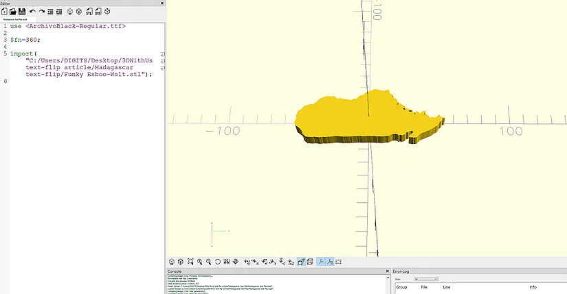
Create a new project folder for the shape-based text-flip, then drag the exported STL into the folder and into your OpenSCAD file. The imported object becomes the starting point for aligning the word.
Choosing and Setting the Font
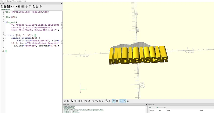
As with the word-to-word example, choose a bold font that prints well. Set up the word in OpenSCAD, adjust the spacing so the letters overlap, and rotate the word so it faces the shape properly.
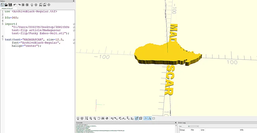
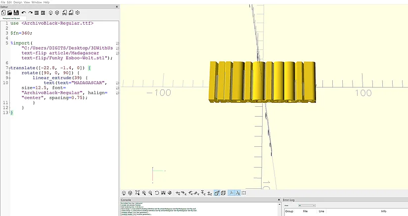
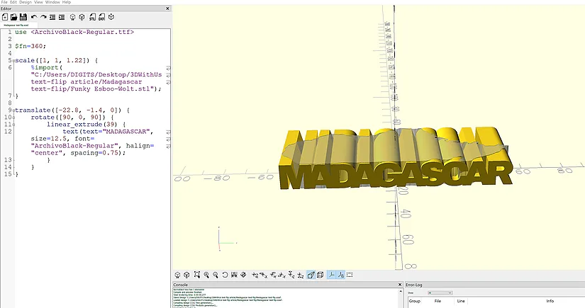
Aligning the Word With the Shape
Use translate, rotate, scale and linear_extrude to make the word and shape overlap as precisely as possible. In this stage, it helps to check multiple views so you can confirm that the text intersects the imported object in all relevant directions.
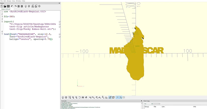
Creating the Final Word-and-Shape Intersection
Once the overlap looks right, place the shape and the word in separate modules, then call them inside an intersection function and render the result. This keeps only the shared volume and creates the final text-flip model.
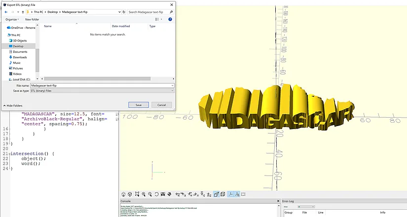
Exporting the Shape-Based STL
Export the finished model as an STL file once the rendered result looks correct.
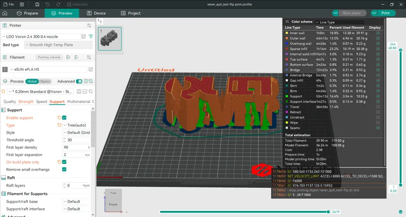
Print Settings
Most text-flip models import into the slicer in a good orientation, but it is still worth checking auto orientation or manually confirming the best face on the build plate before printing.
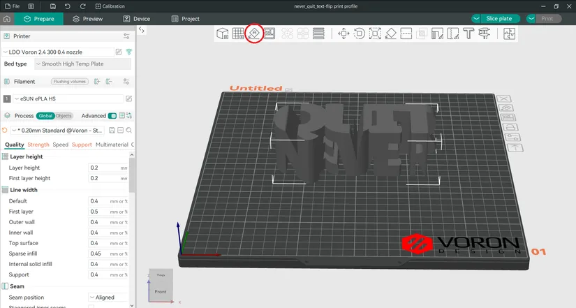
These are the settings used in this guide with good results:
- Layer height: 0.2 mm
- Wall loops: 3
- Top shell layers: 5
- Bottom shell layers: 3
- Sparse infill density: 10%
- Sparse infill pattern: Gyroid
- Support type: Tree (auto)
- On build plate only: Selected
Final Thoughts
Text-flips are a fun way to turn typography and simple shapes into clever 3D print ideas. The process takes some trial and error, especially when aligning the objects, but once the logic clicks, it becomes a flexible method for creating names, motivational words, maps and other personalised designs.
This makes text-flips a strong candidate for maker gifts, desk pieces and creative display prints, especially for anyone who enjoys experimenting with OpenSCAD and custom text-based designs.
Feel free to try these designs by downloading on MakerWorld or Printables. Please don’t forget to share your prints.
Have questions? Feel free to ask in the comment section below.
For a wider discussion or to share your Text-Flip prints, join us in the forum: